Tuesday, February 17, 2015

Thevenin's Theorem

      Thevenin's Theorem states that it is possible to simplify any linear circuit, no matter how complex, to an equivalent circuit with just a single voltage source and series resistance connected to a load. The qualification of “linear” is identical to that found in the Superposition Theorem, where all the underlying equations must be linear (no exponents or roots). If we're dealing with passive components (such as resistors, and later, inductors and capacitors), this is true. However, there are some components (especially certain gas-discharge and semiconductor components) which are nonlinear: that is, their opposition to current changes with voltage and/or current. As such, we would call circuits containing these types of components, nonlinear circuits.
     
     Thevenin's Theorem is especially useful in analyzing power systems and other circuits where one particular resistor in the circuit (called the “load” resistor) is subject to change, and re-calculation of the circuit is necessary with each trial value of load resistance, to determine voltage across it and current through it.


We can calculate the Thévenin equivalent circuit in two steps:
1. Calculate ZTh. Set all sources to zero (replace voltage sources by short circuits and current sources by open circuits) and then find the total impedance between the two terminals.
2. Calculate VTh. Find the open circuit voltage between the terminals.  


Example
Find the Thévenin equivalent of the network for the points A and B at a frequency: f = 1 kHz, vS(t) = 10 cost V. 
 
The first step is to find the open circuit voltage between points A and B:
The open circuit voltage using voltage division:
= -0.065 - j2.462 = 2.463 e-j91.5º
The second step is to replace the voltage source by a short circuit and to find the impedance between points A and B:
  
Here is the Thévenin equivalent circuit, valid only at a frequency of 1kHz. We must first, however, solve for CT's capacitance. Using the relationship 1/wCT = 304 ohm, we find CT = 0.524 uF
Now we have the solution: RT = 301 ohm and CT = 0.524 m F:
Source Transformation


Source transformation 


The source transformation of a circuit is the transformation of a power source from a voltage source to a current source, or a current source to a voltage source.
In other words, we transform the power source from either voltage to current, or current to voltage.


Voltage Source Transformation


We will first go over voltage source transformation, the transformation of a circuit with a voltage source to the equivalent circuit with a current source.
In order to get a visual example of this, let's take the circuit below which has a voltage source as its power source:
Voltage Source Transformation

Using source transformation, we can change or transform this above circuit with a voltage power source and a resistor, R, in series, into the equivalent circuit with a current source with a resistor, R, in parallel, as shown below:

Current Source Transformation

We transform a voltage source into a current source by using ohm's law. A voltage source can be changed into a current source by using ohm's formula, I=V/R.

Example


Let's do an actual example to demonstrate the mathematics of ohm's law, using the circuit shown below:
Voltage source transformation example

Here, we have a circuit with a voltage source of 10V with a resistor in series of 2Ω.
To calculate what the equivalent current source would be, we calculate it using the formula: I=V/R, which is I= 10V/2Ω= 5A. So the equivalent circuit would be:

Current source transformation example


The new power source is now a 5A current source. The resistor value, however, as with all source transformations stays the same. The only thing that changes is it is now in parallel for a current source transformation.
Try out our calculator below. With this calculator, you can try out as many examples as you want. The calculator does source transformations and presents the new circuits with the new values. 


Current Source Transformation


We will now go over current source transformation, the transformation of a circuit with a current source to the equivalent circuit with a voltage source.
In order to get a visual example of this, let's take the circuit below which has a current source as its power source:
Current Source Transformation
Using source transformation, we can change or transform this above circuit with a current power source and a resistor, R, in parallel, into the equivalent circuit with a voltage source with a resistor, R, in series, as shown below:
voltage source transformation
We transform a current source into a voltage source by using ohm's law. A voltage source can be changed into a current source by using ohm's formula, V= IR.

Example

Let's do an actual example to demonstrate the mathematics of ohm's law, using the circuit shown below:
Current source transformation example
Here, we have a circuit with a current source of 2A with a resistor in parallel of 3Ω.
To calculate what the equivalent current source would be, we calculate it using the formula: V= IR, which is V= 2A*3Ω = 6V. So the equivalent circuit would be:
Voltage source transformation example
The new power source is now a 6-volt voltage source. The resistor value, however, again, as with all source transformations stays the same. The only thing that changes is it is now in series for a voltage source transformation.
Again, you can try as many examples as you would like if our calculators below, which do source transformations.


Summary

So, in summary, source transformation changes the circuit's power source from either a voltage source to a current, or a current source to a voltage source, by using ohm's law.
The diagram belows shows the transformation process:
Source transformation

Note- Note also that polarity is observed when source transformation is performed. The positive and negative terminals of the power sources must match when doing a transformation.
If we flipped the voltage source in the above circuit around, we would have to do the same for the current source. Thus, the circuit would then be:
Source transformation polarity flipped

Thus, you can see now that the polarities of both power sources match up. This is important when doing source transformation. If polarity isn't observed, the polarities of the power source will not match and the circuit will be wrong.

Superposition Theorem


     Superposition theorem is one of those strokes of genius that takes a complex subject and simplifies it in a way that makes perfect sense. A theorem like Millman's certainly works well, but it is not quite obvious why it works so well. Superposition, on the other hand, is obvious.
     
     The strategy used in the Superposition Theorem is to eliminate all but one source of power within a network at a time, using series/parallel analysis to determine voltage drops (and/or currents) within the modified network for each power source separately. Then, once voltage drops and/or currents have been determined for each power source working separately, the values are all “superimposed” on top of each other (added algebraically) to find the actual voltage drops/currents with all sources active.


Steps in Superposition Theorem
  1. Turn off all independent sources except one source. Find the output (voltage or current) due to that active source using nodal or mesh analysis.
  2. Repeat step 1 for each of the other independent sources.
  3. Find the total contribution by adding algebraically all the contributions due to the independent sources
 

To calculate the contribution of each source independently, all the other sources must be removed and replaced without affecting the final result.
When removing a voltage source, its voltage must be set to zero, which is equivalent to replacing the voltage source with a short circuit.
When removing a current source, its current must be set to zero, which is equivalent to replacing the current source with an open circuit.
 
Now let's explore an example.

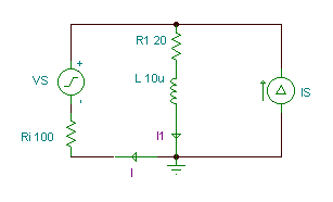
In the circuit shown below,
 
Ri = 100 ohm, R1 = 20 ohm, R2 = 12 ohm, L = 10 uH, 
C = 0.3 nF, vS(t)=50cos(wt) V, iS(t)=1cos(wt+30°) A,  
f=400 kHz. 

  
First substitute an open circuit for the current source and calculate the complex phasors I', I1' due to the contribution only from VS.
The currents in this case are equal:
I' = I1' = VS/(Ri + R1 + j*w*L) 
= 50/(120+j2*p*4*105*10-5
= 0.3992-j0.0836
I' = 0.408 ej 11.83°


 Next substitute a short-circuit for the voltage source and calculate the complex phasors I'', I1'' due to the contribution only from IS.


In this case we can use the current division formula: 


I'' = -0.091 - j 0.246 A 

and 


I1" = 0.7749 + j 0.2545 A 

The sum of the two steps:
I = I' + I" = 0.3082 - j 0.3286 = 0.451 e- j 46.9° A
I1 = I1" + I1' = 1.174 + j 0.1709 = 1.1865 ej 8.28°


The time functions of the currents:
i(t) = 0.451 cos (t - 46.9°) A
i1(t) = 1.1865 cos (t + 8.3°) A